Jon Mitchell's Home
Electronics
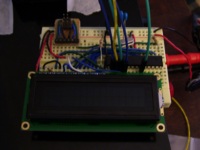
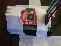
Since I just wanted a quick proof of concept and went with a network module, the overall test circuit was very simple. I just threw a display and micro-controller on a breadboard and connect it to the SPI interface on the network module. Below are close ups of the two boards:


The breadboard on the left is just a simple 30 x 2 conductor breadboard with 2 power rails. I find it is perfect for small projects because you can just fit the project and not waste a huge board for a little project. The circuit consist of a AVR (ATMega328p) micro controller, an 16 charter by 2 line character LCD display with a parallel interface, and a programmer header. I went with a 20MHz crystal which is the maximum for the AVR micro controller I chose, just to max out the speed. After finishing I realized I could have used a slightly slower clock, but it never hurts to be a tad bit too fast.
On the right is the network interface board, WIZ810MJ, which is a breakout board for the W5100 TCP/IP Embedded Ethernet Controller. As you can see from the picture I have a little green board around the nice red WIZ810MJ interface board. This is because the breakout board for the Embedded Ethernet Controller exposes a bunch of pins from the W5100 chip, I however only care about a few. I wire wrapped the pins that I needed to pins on the green circuit board and added the needed resistors while I was at it. This made it very easy to connect to the SPI interface on the W5100 and power the breakout board.
I have made up the circuit diagram for the circuit that I am using. This does not include the WIZ810MJ breakout board, but instead is just the how I would make the circuit without the breakout board, and just using the W5100 chip.